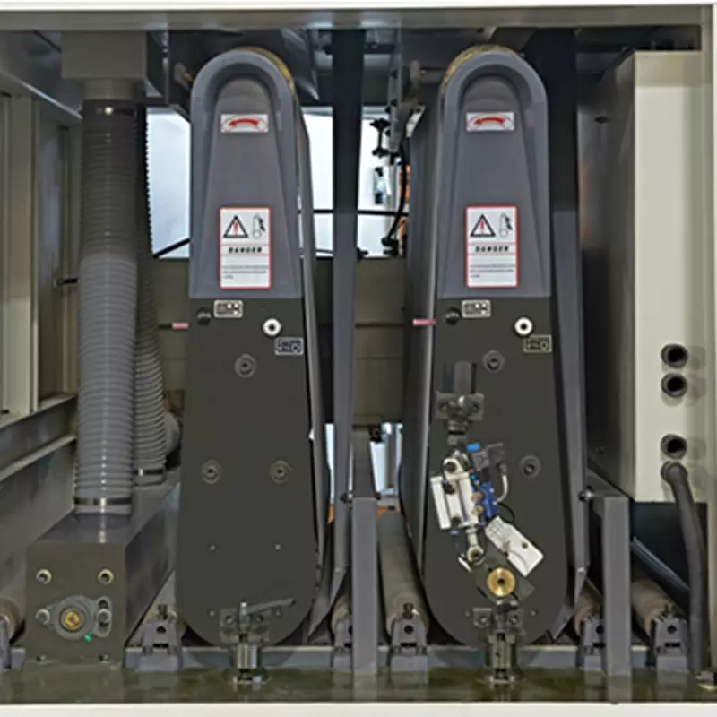
The sanding machine is a precision-engineered equipment designed for surface smoothing, calibrating, and finishing of various materials including wood, metal, glass, and composite panels-. Its robust internal structure integrates multiple coordinated components that work together to deliver consistent sanding quality, operational stability, and processing efficiency-. Below is a detailed breakdown of its core internal structure and key components.
1. Main Frame (Machine Bed)
The main frame serves as the foundational support structure of the sanding machine-. Constructed from heavy-duty welded steel, it provides exceptional rigidity and vibration dampening during high-speed operation-. The frame houses all internal components and maintains precise alignment between the sanding unit and the workpiece conveying system-. Its sturdy design ensures long-term dimensional stability and operational accuracy.
2. Sanding Unit (Abrasion Head)
The sanding unit is the core working mechanism of the machine, typically consisting of the following sub-components:
-
Abrasive Belt / Sanding Belt: An endless loop of abrasive material trained over the contact drum and idler roller. The belt is available in various grit sizes to accommodate rough sanding, fine sanding, and finishing operations.
-
Contact Drum (Contact Roller): Positioned at the bottom of the sanding head, the contact drum is the primary driving component that presses the abrasive belt against the workpiece surface-. It adopts an integral structure manufactured from seamless steel pipes with a wall thickness of approximately 9mm, ensuring uniform pressure distribution and prolonged service life-. The contact drum is driven by its own dedicated motor through a suitable power transmission system.
-
Idler Roller (Tension Roller): Located at the top of the sanding head, the idler roller maintains proper tension on the abrasive belt-. Its bearing blocks are adjustable, allowing operators to fine-tune belt tension for optimal sanding performance.
-
Eccentric Shaft: Precision-machined from round steel, the eccentric shaft connects the contact drum to the drive system. It is manufactured with a balance error tolerance within ±0.02mm to prevent sanding omissions or deviations.
-
Support Frame (Sanding Head Frame): The structural housing that encloses and supports the contact drum, idler roller, and abrasive belt assembly.
3. Drive System
The drive system powers both the sanding unit and the workpiece conveying mechanism:
-
Main Sanding Motor: Provides rotational power to the contact drum, determining the sanding belt speed-. Motor power typically ranges from 4HP to 37KW depending on the machine model and application requirements.
-
Feed Motor: Drives the conveyor system that transports workpieces through the sanding zone-. Feed speed is adjustable via frequency control to accommodate different material types and sanding requirements.
-
Transmission Components: Including gears, pulleys, belts, and bearings that transmit power from motors to the working components-. High-quality NSK bearings are employed at critical connection points to ensure smooth operation and reduce maintenance requirements.
4. Conveying System (Work Table / Feed Conveyor)
The conveying system transports workpieces through the machine at a controlled speed:
-
Conveyor Belt: An endless belt with an upper transport branch defining a substantially horizontal support surface for the workpiece. The belt is driven by the feed motor and moves the material in a given direction through the sanding zone.
-
Work Table: A generally horizontal support surface, often in the form of a conveyor, that holds the workpiece during the sanding process. The table height can be adjusted to accommodate different workpiece thicknesses.
-
Feed Rollers: Multiple rollers that guide and stabilize the workpiece as it enters and exits the sanding zone.
5. Adjustment Mechanism
Precision adjustment systems allow operators to fine-tune sanding parameters:
-
Height Adjustment: Regulates the vertical position of the sanding unit relative to the work table, accommodating workpieces of varying thickness.
-
Gap Adjustment: Controls the distance between the sanding belt and the workpiece surface, determining the depth of material removal.
-
Belt Oscillation Mechanism: Ensures the abrasive belt oscillates laterally across the contact drum, promoting even belt wear and extending belt life.
6. Dust Collection & Cleaning System
Integrated dust removal features maintain a clean working environment and protect internal components:
-
Internal Hood: Encloses the sanding unit to contain chips and dust generated during operation.
-
Dust Extraction Port: Connects to an external dust collection system to remove airborne particles.
-
Cleaning Assembly: Operatively coupled to the abrasion unit to remove debris from the sanding belt and surrounding areas.
Key Features & Advantages
Applications
This sanding machine is suitable for surface smoothing, calibrating, and finishing of flat panels made from wood, wood products, fiberglass, plastic, metal, and composite materials. It can be integrated into automated coating and finishing lines or used as a standalone unit for precision surface preparation.